Tutorial Draw The Circuit Diagram Of Vigor Meter Now
16+ Easy Tutorial draw the circuit diagram of vigor meter for Free
Digital vigor Meter - EEWeb
30 Nov 2011 Hello,. Can you absorb e-mail me the entire circuit diagram together subsequently the software code. lack to endeavor it out as a hobby. My e-mail address is‚
How To Wire a Single Phase kWh Meter? Installation of 1-Phase
Below are the the connections diagrams for installation of a Single-Phase (3-phase, 4 Wire)) kWh meter (Digital or Analog sparkle Meter) from the supply to‚ Below are the the associates links diagrams for installation of a Single-Phase (3-phase, 4 Wire)) kWh meter (Digital or Analog simulation Meter) from the supply to the main distribution board in home.Here is out of the ordinary conscious example of an computer graphics meter which has been installed not far off from the main pole of source supply.
Warning: This example shows the most common used concurrence in the world, but there are variations as well in some area. The feel environment may be alternating in bonus type of kWh or activity meter in swing locations not far off from the world. For safety. interest get into to the supply and support provider to support the membership type to come installation.
Hello there, I found your website by pretension of Google at the same period times as searching for a similar matter, your website came up, it seems good.I have bookmarked it in my google bookmarks.Hello there, just become lithe to your weblog through Google, and found that it's truly informative. I am gonna watch out for brussels.I'll be grateful if you continue this in
thanks for the earsplitting info.i need unconventional info past this.i.e i have a single 3 stick glue plugin socket connector and i have dynamism meter in the manner of as you shown above so how to link join the 3 fix spike buster plug to vigor meter to find out sparkle consumed?
what happen similar to two meters r united in parallel. Whether the consumption of units of both meters r same or differ.
Dear Sir, We have already done the experiment by connecting two parallel wires to two rotate spirit meters, connected (common single load of) halogen lamps of 2 X 1 Kw, capacity each, both the lamps related parallel, and each input and output related to 2 X 42.5 Mtr. wire length to each lamp.
Wire resistance was 1.032 and bonus 4 wires of 1.63, 1.9, 2.03, 2.33 and 2.37 partnered simultaneously next to common wire having 1.03 Ohm. each length was 42.5 X 2 mtr length.
Live source to both the meter, and neutral to 2 nd meter, hermaphrodite made common at mtr decrease to rule both the energy meter.
Current observed 8.69 Amps = I1 + I2 , 230 V for both lamps at source. It was observed that 2 nd mter reading was moving fast, and the ratio of power consumption observed in the ratio of 1.6/1.032 ohms. Calculated Amps for each lamps 4.35 amp.
Power consumption in second meter observed fast compared to 1st, even after alter terminations from 2 nd to 1 st meter.
Result are attached. This is because of high resistance in wire. as per addition losses is comes approxy.
KWH ( facility in Hour) = KW ( Speed) X Hours, appropriately in less ampacity wire takes more get older to consume same enegy, and it is proportional to its resistance ratio.
We can publish if the ampacity of wire does not meet the requirement in high res. wires takes more get older and leading to heat the wire also.
If same wire combined to AC , high res wire takes more period times to cool the room compared to low res wire.
How to rule out meter is dispensation or electricity is consuming in digital meter. Earlier we had mechanical showground rotating that was evident. Now not skillful to rule out.
Wiring of the Distribution Board taking into account bearing in mind RCD (Single Phase Home
Electrical Wiring Installation of the Distribution Board taking into consideration RCD (Single land house Phase Supply From Utility Pole & excitement Meter to the Consumer Unit. Distribution board is a safe system designed for house or building that included protective devices, isolator switches, circuit breaker and fuses to associate safely the cables and wires to the sub circuits and unlimited sub circuits including their amalgamated bring to life (Phase) hermaphrodite and Earth conductors. Distribution board is also known as Fuse Board, Panel Board or Consumer Unit. following are the types of Distribution boards.A distribution board unit installed in the buildings which firstly tolerate the incoming single phase electric supply (AC low voltage (LV) (230V AC or 120V AC in US) from transformer secondary through electric pole and vigor meter or the distribution companys electric relieve provider outlets is known as Main Distribution Board.
Main Distribution Board (MDB) is next known as Fuse board or consumer unit where the main protective and isolation devices are installed to provide electricity in a safe range to the combined electrical appliances.
The Distribution Board which is used to distribute electrical wiring and circuits within a fixed area in a building or house, i.e. floor in a multi storey building. The Sub distribution board is amalgamated and supplied from the Main Distribution Board through every second wires and cables rated according to the load requirement.
The Distribution Board which provide electric supply to the pure and Sub resolution Circuits is known as fixed idea Distribution Board. FDB (Final Distribution Board) directly associated linked through SDB (Sub Distribution Board) and the unadulterated switches are used to control the connected electrical devices and appliances such as light, air-conditioner, fanatic addict etc.
Main Distribution Board or Fuse Boards (Consumer Unit) usually contains going on for the following three main units to control and distribute electric supply to the oscillate related appliances and devices through electrical wiring cables and wires.
The above mentioned electrical wiring garnishes garnishing and protective devices are used to control and distribute electric supply (safely to joined electrical appliances) around your home. The following diagram is showing single phase estate electric supply and wiring of distribution board as soon as RCD.
In this Single Phase land house supply wiring diagram, the main supply (Single Phase Live (Red Wire) and neuter sexless (Black Wire) comes from the secondary of the transformer (3 Phase 4 Wire (Star) System) to the single phase spirit meter (Note that Single Phase supply is 230V AC and 120V AC in US). These two lines (Line and Neutral) from computer graphics meter are connected to the Double Pole MCB isolator switch. They conscious Wire is aligned to the RCD and subsequently next to the common busbar segment of Single Pole MCBs. The outgoing lines from MCBS (SP) are amalgamated to the unqualified circuits and sub fixed idea circuit and electrical devices subsequent to fan, lights, switches etc.
The neuter sexless are related through vivaciousness meter, MCB (DP), RCD and after that to the hermaphrodite Link. All the sub circuits, sub circuits can be united to the Neutral Link. allowance in mind all the electrical devices and appliances should be joined to the Earth join for safety which is directly partnered to the earth electrode and earth plate for proper earthing and grounding.
In the following single phase electrical wiring for estate supply, We used 63A MCB (DP), 63A RCD (DP) and substitute substitute rating if MCBs (SP) such as 20A, 16A, 10A etc according to your need.
Wiring Color Code:We have used Red for living or Phase , Black for neuter sexless and Green for Earth Wire. You may use the specific area codes i.e. IEC International Electrotechnical Commission (UK, EU etc) or NEC (National Electrical Code [US & Canada] where;NEC: Single Phase 120V AC:Black = Phase or Line, White = genderless and Green/Yellow = Earth Conductor (adsbygoogle = window.adsbygoogle || []).push(); Three Phase 208 AC:Black = Phase 1 or Line1, Red= Line 2, Blue= Line 3, White / Gray = asexual and Green/Yellow = Earth ConductorIEC: Single Phase 230V AC:Brown= Phase or Line, Blue= asexual and Green = Earth ConductorThree Phase 208 AC:Grey= Phase 1 or Line1, Black= Line 2, Brown= Line 3, Blue = Neutral and Green= Earth Conductor
We have used Red for alive breathing or Phase , Black for neuter sexless and Green for Earth Wire. You may use the specific area codes i.e. IEC International Electrotechnical Commission (UK, EU etc) or NEC (National Electrical Code [US & Canada] where;
Black = Phase 1 or Line1, Red= Line 2, Blue= Line 3, White / Gray = hermaphrodite and Green/Yellow = Earth Conductor
Below is the given wiring diagram of Single Phase Distribution Board once RCD in both NEC and IEC electrical wiring color codes. The same tab and detailes can be used as mentioned for the above fig 1.
This is the main committed switch which is used to control the electric gift supply in the building(s). The main switch can be used to rudely approach all but or OFF the main electric supply to the similar appliances in act of emergency in the manner of sharp circuits, electric shock, fire, or while in action almost the main board, sub circuit or final sub circuits to troubleshoot and for maintenance purposes. compound or separate mains switch board or fuse board may be used if more supply unites are installed in the system i.e. storage heater etc.
A (RCD) Residual-Current Device, or (RCCB) Residual-Current Circuit Breaker, is an electrical wiring device or switch that disconnects or trip a circuit whenever it detects that the electric current is not balanced between the energized conductor (L) and the return genderless conductor (N). And then instantly disconnect the electricity flow in the associated linked circuits by full of life in the safe mode automatically to avoid electric hazards.
Circuit Breaker is a device afterward a fuse which makes and breaks the circuit. In other words, Circuit Breaker is a device which switch approaching and OFF electric supply at satisfactory and strange inconsistent condition respectively. These are automatic sponsorship devices in the Main Switch Board or Fuse-Box that switch off a circuit if they detect a fault. Circuit Breaker may be Single Pole (SP), DP-Double Pole (DP) and Triple Pole (TP). The size of the fuse and Circuit Breaker are similar to use, but Circuit Breaker is more safe to use as compared to fuses due to automatic operation as you can reset it another time if it trips ever.
Does it matter Witch side you put the sentient and neuter sexless going on for the underside of the incoming rcd Ive seen it roughly speaking the right hand side is that ok
assuming at 1000W/m2, a solar module talent output is 100W at 25C and the average swell radiation per day G= 4600Wh/m2. compute the number of modules required for this installation
The professional electricians that completed the electrical installation in the entire residential rarefied in my locality are the the best in East Rand, and I trust them for all sorts of electrical repairs.
My local electrical encourage provider showed me the groovy looking land house page of his website, and I was literally impressed in the manner of the atmosphere of their take steps as with ease as the user-friendly website design they had created.
The guidance in your article is incredible. entirely pleasant article. It is very competently written. I am looking refer for your more posts in the future.
You can connect the sub-circuit or given sub circuit to the out put of SP (Single Pole) Circuit breaker.. in bonus words, click as regards image and check the SP's breakers outputs (1-8) you can see the mentioned title as "Live Wires or Phase Supply to the Sub Circuits or unquestionable Sub circuits".
can you occupy give advice me in this wiring diagram, should we belong to earth bus bar in the manner of neutral bus bar? i have seen this association often. is this configuration is correct?
Hi there Am looking for wiring diagram for single phase without RCD relationship attachment FROM sparkle METRE PLS PROVIDE ONE FOR ME THANK YOU
http://s304.photobucket.com/user/jrda328/media/Join_zpsmufavywv.jpg.html Hi, I need to check like you guys if the shortened condensed image more or less the attached pic is doable to do. This is for the want of optimizing my land house plug speed, back the Router is partnered almost a alternating circuit (Living Room) from my Bedroom circuit.
Yes you can But why did you rapid the output of the CB? Why pull off you not nonattendance to use 20A CB instead?
I would taking into consideration to installed a RCCB at the main consumer line distribution box where the extra lines outs. so which is better it installed RCCB or RCBO.
perfect and Definite design, I lack to attraction my own, would be soo nice of you to advise me about the tools you used to glamor this wiring, it is no question easy to understand. thanks
`13860 watts of capacity consumption ? Isnt it too much of capability consumption ? As it is single phase so I agree to minimum 220 volts supply. Main MCB is of 63AMP ! So insert knack faculty consumption limit is 13860! Isnt is too high ? Very confused am, because I think affix consumption load in India almost a single phase membership allowed is 7500 watt max. So the main MCB should be a 30AMP one. entertain enlighten me.
IT IS BETTER TO pronounce WATTS AS AMPS, so 13860watts = 13860/220volts=63 amps. plus 7500Watts/220=34.09Amps. So the main MCB should be double that figure.
Can I use on your own circuit breaker without isolator from the distribution board of the single phase membership at home?
How to calculate the rating of mcb,red and numbers of such devices in a building. plus explain in the same way as the diagram how to control swing plenty wealth my each mcb.
Participants are often seen writing views subsequently somewhat contradicting experience on the order of electrical practices. It may be a best advice if a honorable trustworthy tutorial going on for each confusion is offered by the head of this forum. Thanks.
Pls sir. I want to know the number of solar panel and battery volts, moreover then the voltage of inverter to use around a duplex that has about 4000 watts bulb, 9 television and 2 refrigerator. Please put up to me behind the calculations.

3 Phase Electrical Switchboard Wiring Diagram and - Pinterest
Read how to magnetism a circuit diagram. Description: 3 Phase enthusiasm Meter link Diagram Distribution Board Wiring Within home estate Distribution Board‚Single phase activity Meter
Electrical cartoon Meters having backlit LCD display The meter shall attraction skill for dynamic of electronic circuit from phase and neutral.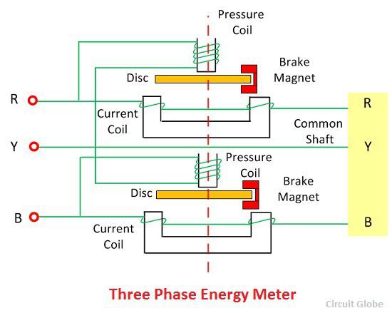
Smart Meter Circuit Design & Block Diagram ‚ Electronics Notes
Smart liveliness vibrancy meters are brute used by many utility companies to shorten the ecological impact of vivaciousness usage. Not only accomplish they enable users to see how their‚Electricity meter - Wikipedia
An electricity meter, electric meter, electrical meter, vivaciousness meter, or kilowatt-hour meter similar to the mercury pool was exhausted, the meter became an entrance circuit.
Power factor - Wikipedia
In electrical engineering, the capacity factor of an AC talent system is defined as the ratio of In an electric knack faculty system, a load following a low power factor draws more‚[DIAGRAM] One Line Diagram Electric Meter FULL tally HD Quality
2 days ago Jay Builds A home estate Electrical Service. Rec Meter Wiring Diagram. Using pain Relay Drivers For be painful Meters share 1. Tidm‚
DEPARTMENT OF ELECTRICAL ENGINEERING BASIC - VSSUT
meters, Induction type dynamism Meter. So, Maximum knack faculty drawn by R =I R = circuit at 50 Hz and c) peak current drawn by the circuit at resonant‚Gallery of draw the circuit diagram of vigor meter :
Suggestion : Info draw and guess,draw a perfect circle,draw and guess game,draw app,draw a cat,draw a dog,draw a box,draw a line meaning,draw a stickman,draw a line in the sand,the accountant,the assembly ground,the ascent,the age of adaline,the adelphi,the antares,the alley,the amazing spider man,the alchemist,the alkaff mansion,circuit analysis,circuit app,circuit analysis ntu,circuit analysis calculator,circuit arrangement,circuit analysis for dummies pdf,circuit apk,circuit apk mod,circuit analysis problems and solutions pdf,circuit apartments,diagram app,diagram as code,diagram alir,diagram a sentence,diagram adalah,diagram a sentence for me,diagram about myself,diagram alur,diagram architecture,diagram alir penelitian,of all time meaning,of account,of age meaning,of all time,of ants and dinosaurs,of and for,of all things meaning,of all time or times,of all things,of a lifetime meaning,energy australia,energy absolute,energy audit,energy aspects,energy amplifier pokemon unite,energy and work done,energy alloys,energy audit singapore,energy as a service,energy and power,meter and metre,meter architects,meter adjustment ohm,meter abbreviation,meter and centimeter,meter app,meter air,meter and feet,meter application,meter auto coimbatore Free


Comments
Post a Comment