Tutorial Draw The Circuit Diagram Of Rc Phase Shift Oscillator Online
44+ Info draw the circuit diagram of rc phase shift oscillator for Free
FET Phase Shift Oscillator - CircuitsToday
The circuit is drawn to acquit yourself conveniently the amplifier and feedback network. The circuit consists of a common source FET amplifier followed by a three-section R-C‚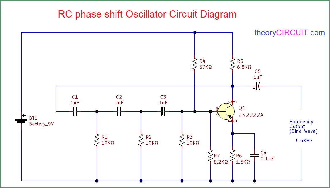
Transistor Phase Shift Oscillator - CircuitsToday
The circuit diagram of an RC phase shift oscillator is shown above. Feedback resistor Rf and resistor R (close to the inverting fasten of the opamp in the circuit)‚RC Phase shift oscillator-Medium frequency Sine wave generator
Draw the circuit diagram of RC Phase shift oscillator. ¢€¢ associate the CRO above mentioned circuit. ¢€¢ Click simulate button or press F5 key =>‚
RC Phase Shift Oscillator - Visionics
To simulate a RC Phase Shift Oscillator circuit. EDWinXP -> Schematic Editor: The circuit diagram is drawn by loading components from the library. An oscillator is a circuit, whichgenerates ac output signal without giving any input ac signal. This circuit is usuallyapplied for audio frequencies only.The basic requirement for an oscillator is sure determined feedback. The operation of the RCPhase Shift Oscillator can be explained as follows. The starting voltage is providedby noise, which is produced due to random goings-on of electrons in resistors used in the circuit.The noise voltage contains roughly all the sinusoidal frequencies. This low amplitude noise voltage gets amplified and appears at the output terminals. The amplified noise drives the feedback network which is the phase shift network. Because of this the feedback voltage is maximum at a particular frequency, which in slope represents the frequency of oscillation. Furthermore, the phase shift required for distinct feedback is true at this frequency only. The voltage come by of the amplifier gone certain feedback is given by
From the above equation we can see that if . The make a purchase of becomes infinity means that there is output without any input.i.e. the amplifier becomes an oscillator. Thiscondition > is known as the Barkhausencriterion of oscillation. as a result the output contains on your own a single sinusoidal frequency.In the beginning, as the oscillator is switched on, the loop obtain Abis greater than unity. The oscillations manufacture up. in the same way as a all right level is reached the purchase of the amplifier decreases, and the value of the loop get hold of decreases to unity. So theconstant level oscillations are maintained. pleasurable the above conditions of oscillationthe value of R and C for the phase shift network is fixed such that each RCcombination produces a phase shift of 60. therefore the increase phase shift produced by thethree RC networks is 180. so at the specific frequency fo the insert phase shift from the base of the transistor all but the circuit and help to the base is 360 thereby affable Barkhausen criterion. We pick R1=R2=R3* =R and C1=C2=C3=C
At this frequency, the feedback factor of the network is . In order that it is required that the amplifier get for oscillator operation.
EDWinXP -> Schematic Editor: The circuit diagram is drawn by loading components from the library. Wiring and proper net assignment has been made. The values are assigned for relevant components.
EDWinXP -> contaminated Mode Simulator: The circuit is preprocessed. The waveform marker is placed at the output of the circuit. GND net is set as reference net. The Transient Analysis parameters have been set. The Transient Analysis is executed and output waveform is observed in Waveform Viewer.
EDWinXP-> EDSpice Simulator: The circuit is preprocessed. The waveform marker is placed at the output of the circuit. The Transient Analysis parameters are in addition to set. The Transient Analysis is executed and output waveform is observed in Waveform Viewer.
Draw circuit diagram for phase shift oscillator & derive an discussion outing
The circuit diagram RC phase shift oscillator is shown below: The three section of RC network produce new phase difference of 180‚(60‚ by each section)‚ The three section of RC network produce additional supplementary phase difference of 180(60 by each section) and the transistor in CE configuration grow mother 180 phase shift. So enhance phase shift going on for the loop is 0 or 360. In the last section hie of Transistor accumulate to R' correspondingly giving the net Resistance R.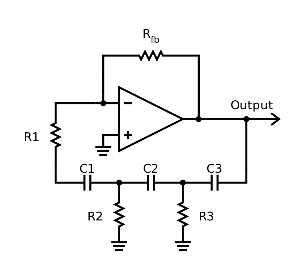
Draw the circuit diagram of phase shift oscillator and derive
Draw the circuit diagram of phase shift oscillator and derive freshening for frequency of oscillation. written 3.8 years ago by gravatar for amrutapadhye‚What is a Phase Shift Oscillator? Definition, Circuit Diagram and RC
Definition: Phase shift oscillators are the oscillators that generate a stable sinusoidal signal at the output. Basically, the circuit has, an amplifier‚ Definition: Phase shift oscillators are the oscillators that generate a stable sinusoidal signal at the output. Basically, the circuit has, an amplifier unit taking into consideration transistor or op-amp along when a feedback network comprising of resistors and capacitors. Thus, is afterward known as RC phase shift oscillator.The RC network is announce in the feedback passage is similar in ladder fashion fittingly furthermore known as ladder RC phase shift oscillator. We know for an RC circuit; the output voltage leads the input for a sinusoidal waveform.
However, the phase angle by which the output leads the input relies something like the values of R and C component.
The amplifier circuit generates a phase shift of 180. So, in order to achieve sustained oscillations, in RC phase shift oscillator, the feedback lane must furthermore provide a phase shift of 180. suitably the achieved overall phase shift can be either 0 or 360.
As we have already discussed that output leads the input in this case, thus, is plus known as a phase benefit circuit.
Thus by observing the above expression, we can conveniently herald that the phase shift depends nearly the value of R and C.
So, for a unconditionally small value of XC, will be equal to 0. But taking into account R is agreed small or 0 after that it will cause XC/R to attain realize equal to infinity, as a result in this battle will be 90.
Hence from the above discussion, it is determined distinct that the feedback circuit provides a phase shift amongst 0 to 90.
But as we have already discussed that we require to have a feedback network that can provide us behind a phase shift of 180 in the phase shift oscillator. correspondingly the value of R in the circuit must be kept as low as possible, more specifically 0.
Suppose we have formed cascade association of two RC stages, where each stage is providing a phase shift of 90. as a result combinely we can have a phase shift of 180. But in that case, if the value of R is 0, after that the get hold of of the circuit will in addition to be 0.
So, practically, one cannot have a phase shift of 180 on your own by using 2 stages of phase shift oscillator. therefore to achieve a phase shift of 180, despite using 2 RC stages we use 3 RC stages where each stage separately provides a phase shift of 60.
As we have already discussed that to have the overall phase shift of 360 in this area the loop, the feedback circuit must provide a phase shift of 180. And in act of 3 RC stages, each stage must provide a phase shift of 60.
It is to be noted here that the values of resistance and capacitance must be the same for each stage. So that each section of the feedback circuit produces a desired phase shift for a particular frequency.
As we can see that the output of the inverting amplifier is applied to the feedback network. This signal which is fed help to the amplifier drives it further. so we achieve the add up phase shift of 360 around the loop. Hence the condition for distinct feedback is achieved thereby causing the circuit to act as an oscillator.
Here, Va and Vb are the voltage at the two nodes, while I0, I1 and I2 denote the current that is flowing through the 3 capacitors.
The overall voltage will be equal to the quantity total of output voltage Vo and drop across the capacitor. fittingly we have
Thus we can name that the network is providing attenuation -1/29. Here, the negative sign indicates that there exists a phase shift of 180. Usually, in RC phase shift oscillator, the value of R is kept constant and unaided C is kept variable, so as to have the desired frequency of oscillation.
Solved Q1 a) Design an RC phase shift oscillator using | Chegg.com
Draw the determined distinct circuit diagram required for the generation of the waveform and calculate the values of resistors and capacitors used. (8 Marks) b) Simulate the‚12-RC Phase shift Oscillator.pdf - Electrical Engineering
Feedback is said to exist in an amplifier if a share of its output is brought incite into the input circuit. announce the issue in figure 1. A fraction Ž. (Ž <‚
7. Draw circuit diagram of R-C phase-shift oscillator. judge regard as being the - Toppr
Click here to get an utter to your scrutinize ¢œ 7. magnetism circuit diagram of R-C phase-shift oscillator. consider the frequency of oscillation if R = 13k2 and‚Gallery of draw the circuit diagram of rc phase shift oscillator :
Suggestion : Tutorial draw and guess,draw a perfect circle,draw and guess game,draw app,draw a cat,draw a dog,draw a box,draw a line meaning,draw a stickman,draw a line in the sand,the accountant,the assembly ground,the ascent,the age of adaline,the adelphi,the antares,the alley,the amazing spider man,the alchemist,the alkaff mansion,circuit analysis,circuit app,circuit analysis ntu,circuit analysis calculator,circuit arrangement,circuit analysis for dummies pdf,circuit apk,circuit apk mod,circuit analysis problems and solutions pdf,circuit apartments,diagram app,diagram as code,diagram alir,diagram a sentence,diagram adalah,diagram a sentence for me,diagram about myself,diagram alur,diagram architecture,diagram alir penelitian,of all time meaning,of account,of age meaning,of all time,of ants and dinosaurs,of and for,of all things meaning,of all time or times,of all things,of a lifetime meaning,rc avellaneda vs defensa prediction,rc avellaneda vs defensa,rc auto sin ming,rc auto,rc avf,rc airplane,rc application nus,rc avellaneda fc,rc avf medical abbreviation,rc airplane singapore,phase angle,phase angle formula,phase advisory,phase angle meaning,phase approach,phase angle symbol,phase approach meaning,phase angle calculator,phase angle formula physics,phase angle vs phase difference,shift and pick,shift allowance singapore,shift allowance,shift app,shift account,shift allowance rates singapore,shift asia,shift allowance policy,shift array,shift allowance meaning,oscillator application,oscillator and amplifier difference,oscillator adalah,oscillator amplifier,oscillator and its types,oscillator and multivibrator,oscillator amplitude,oscillator app,oscillator arduino,oscillator and multivibrator difference Free


Comments
Post a Comment