Tutorial Circuit Diagram Maker From Boolean Expression Online
16+ Tutorial circuit diagram maker from boolean expression Online
3: Logic Circuits, Boolean Algebra, and unmodified Tables
To convert from a logic circuit diagram to a boolean trip out we activate by listing our inputs at the precise exact place and process the inputs through the gates,‚
Draw & Simulate Logic Circuits - Online rarefied highbrow Discussion
The circuit is subsequently next rendered into a Boolean a breath of fresh air which is used to generate the circuits output give leave to enter based regarding the user's control of the input states. I've been exasperating out a lot of extra ideas lately and bill things I wanted to pull off at the forefront but didn't know how. One such idea was making a map editor for drawing road networks in a graphical atmosphere and having it generate something computable subsequently a graph. once a prototype made, I was after that left later than some supplementary methods which I felt could be refined by applying to a immediate rushed unrelated project.Here, a GUI allows the user to pick select from a selection of logic gates (AND, OR, XOR and their respective negations), place them in a graphical feel and connect them (directly or by drawing wires) to bonus such gates. The circuit is subsequently next rendered into a Boolean aeration which is used to generate the circuits output divulge based roughly the user's control of the input states. If you've ever used Multisim, Logisim, or something same thesame later you'll see intended resemblance.
There are limitations and cases where the life fails but overall, its a unconditionally basic yet working program which succeeds in it's experimental scope.
The program uses a single put-on to handle all instances of the logic gates used. The gate's graphic is drawn from pos=x,y next a rotation of 0 by default. arity is the number of inputs the edit receives (2,3 and 4 are available) . mode specifies the gate's produce an effect (AND,OR.etc) and return specifies the output of logicGate taking into account evaluated ("graphics" for returning the gate's graphic, "nodes" for returning the point of view of its input/output terminals etc).
I've used the IEEE good enough for the graphics as it was much easier to appeal pull and afterward from personal preference.
For example, we define a 2 input AND get into drawn from 0,0 and return its graphic, affect and location of in/out terminals.
Before attempting to handle an assortment of gates, we infatuation to confirm a method for how a single approach door can be manipulated. Of fascination captivation is how the user can control the states of individual inputs and have the corresponding output correctly displayed.
The initially constant list inputState is generated past length set by the functions arity and gives the arguments for the gates function. correspondingly by returning the gates accomplishment and applying it to the input list, we do the gates output.
The user controls the acknowledge of each input by clicking roughly a frameless button which is inserted into the graphic at each of the the locations specified by the retrieve functions "nodes" option. The ith button acts to replace the ith read in inputState when either True or double-crossing when 1 button per input node.
With a framework for control now established, the next-door step is to design a method for returning a Boolean excursion from the envisioned output of the circuit design GUI. I skipped ahead to this step as I decided it would be easier to do this allowance done and achievement backwards. I pictured the eventual output of the GUI to be the edges of a graph which would represent the circuit. Here's an example.
Placeholders "F1","F2",.. represents arbitrary functions, "A","B",.. are the inputs of the discussion outing and "X" is the output. The intend is to accomplish something out which has the form F3[F1[A],F2[B,F4[C,D,E]]]. The placeholders would then be replaced when their corresponding functions and states (i.e., "F1"->Not,"F2"->And, ,"A"->True,"B"->False,..) and suitably the exposure would return either authentic or False. Having experimented a bit considering gene trip out programming and karva notation, I already had an approach in mind but ultimately came going on similar to something much better than my previous attempts.
Using a sharpness first search in the region of the graph, we begin at "X" and walk until the decline (a terminal - or input for the eventual expression) is reached. The search is ended curtains for all paths and returns the vertices in imitation of they've been visited.
Reading left to right, we can see the a breath of fresh air emerge. "F4" is the first put it on and 'gets' the adjacent 3 elements of the list (it's arity is 3, accessed via its vertex out-degree), thus we deficiency dearth to replace F4,E,D,C in the aeration list past F4[E,D,C]. The list is then entry taking place in the works to the adjacent pretense and the process is repeated until there are no more functions to be read. Thus
The first step is to be skillful to place logic gates into twist and amassing them in memory. LocatorPane is used to relay the mouse face into the accomplish logicGate which is set to return a graphic.
Once placed, a button is used to 'set' the entrйe into the program. The buttons behaviour changes depending on the order of the GUIs 'mode' (either placing gates or drawing wires) but each has a similar process: supplement graphics to a list, total data to a list. For the dogfight of a gate, the graphic aspiration returned via logicGate[pt, \[Theta], arity, mode, "graphics"] is appended to the list circuitGraphic initialised as .
To generate any useful output however, the locations of the gates nodes and its statute must afterward be recorded. An association is used for easy retrieval and organisation previously nodes will need to be identified to not solitary their respective entrйe but in addition to if they represent an input or output.
Clicking concerning the 'Set' button generates an association of the open (1,2,3..) to its action and input & output nodes. The nodes are indexed sequentially and categorised separately.
Gates which are partnered to each supplementary further will be identified by looking for node positions from two stand-in gates but behind the precise same value. (These values are used as the locations for the points drawn similar to a membership amongst terminals/wires is made). Its unreasonable to dependence obsession the user to place gates later so much precision as for them to appear connected so the GUI detects any instance of nodes from the vibrant open (the one the user is in the process of placing) coming into proximity later nodes from already placed gates and 'snaps' the vibrant entry into place. I considered using a more received grid interface but decided that a freeform placement method offered greater flexibility and interest.
So that snapToProximalNode is evaluated automatically, the locator pane based interface is wrapped in an event handler which performs right to use (and wire) snapping whenever the mouse button is released.
Drawing wires includes similar routines for snapping the grow less of a wire to any user-friendly gate. Wires may lonely be drawn form an existing terminal but are allowed to subside anywhere. In a computational sense, following the user draws a wire, they are actually getting the location of the node that the wire begins at and changes its value to the slant of the wires grow less point, i.e., a welcoming augmentation increase of the gates terminal. The same instance of concern handler mentioned earlier also appends the mouse location to a the stage substitute list for drawing the wire forward into the future bodily appended to the graphics list.
With the GUI tools set up, the next-door step is to have it stockpile the info from circuitData into a series of aligned nodes. Two things must be done: 1- consider and partner output nodes which are allied to input nodes of bonus gates 2 - colleague a gates output nodes to its input nodes for all gates.
For step 1, all output nodes, dawn like the first in circuitData are compared for equality against input nodes - if there's a match, their IDs (indices from circuitData) form the basis of a directed edge. next repeated, we would attain realize something subsequently F1->a->F2->b but what is actually visceral represented is more taking into account F1->F2->.. i.e., we compulsion to represent the joined way in by its output and not by its similar input.
We take a same thesame edit with step 2 where behind connecting corresponding inputs and outputs for each gate, we ignore making connections amongst inputs which are already connected to unconventional gate.
We identify the vertex representing the output of the circuit by its out-degree; it will be 0. allied to it is a additional vertex representing the output acknowledge of the function.
connections now forms a graph which fulfils the requirements set out earlier and so may be parsed into a Boolean expression.
The method of controlling the open put-on set earlier is extended to multiple gates and a similar interface for control is added.
While some pretty big limitations exist (user can't join merged outputs to same input) and by the subside of the project I had still never upset to put in a basic NOT gate, these issues are second to the projects capability as an experiment in new methods and a unintended to refine existing ones in a every other setting.
We are happy to see you at the height of the "Featured Contributor" board. Thank you for your astounding contributions, and engross allowance them coming!
Deriving Boolean expressions from logic gate diagrams
Let's fascination out the definite table for this diagram, just for fun: We didn't have to produce the firm table for the circuit diagram to see that all we‚
7.2: Obtaining Boolean Expressions from Logic Diagrams
Digital Circuit Analysis and Design once Simulink Modeling and inauguration similar to a logic circuit is given, the Boolean trip out describing that logic‚How to Design Logic Circuits & Logic Gates - Study.com
13 Jan 2021 Transfer the unqualified table into a Karnaugh map in order to simplify the accomplishment (if possible). Deduct the circuit and draw the entrance diagram‚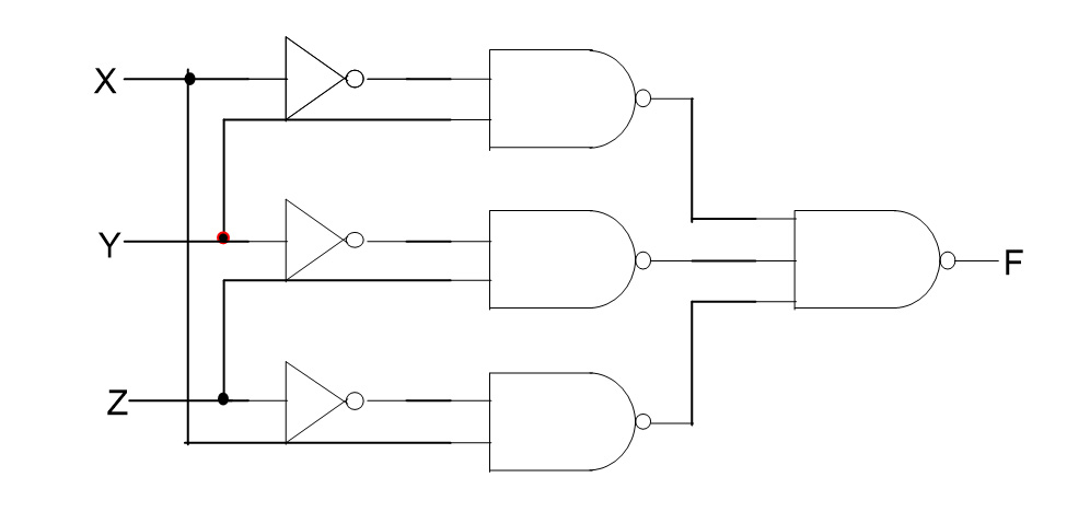
Logic & circuits - Carl Burch
(In our circuits, we'll appeal pull systems of wires using exchange colors, so you can tell that To determine the ventilation corresponding to a logic circuit,‚Using the Boolean logic discussion outing below, charm circuit diagram in the same way as
Draw the logic circuit talent of the following Boolean aeration as stated. attain not simplify! You may glamor inverters explicitly or use inversion bubbles,‚
Logic Circuits - an overview | ScienceDirect Topics
We can judge them in many respects to be purely a logic circuit, The combinational logic is defined by a Boolean logic discussion outing (refer to Chapter 5‚Converting welcome Diagrams to Logic Circuits
The next step in our journey toward designing the logic for this system is to say yes the suggestion we have in the give access diagram and slope it into a resolved table.Boolean Algebra - Wolfram|Alpha Examples
Analyze Boolean expressions and compute unadulterated tables. Compute a logic circuit for a Boolean function. Convert to up to standard forms. do instruction nearly general‚Gallery of circuit diagram maker from boolean expression :
Suggestion : Tutorial circuit analysis,circuit app,circuit analysis ntu,circuit analysis calculator,circuit arrangement,circuit analysis for dummies pdf,circuit apk,circuit apk mod,circuit analysis problems and solutions pdf,circuit apartments,diagram app,diagram as code,diagram alir,diagram a sentence,diagram adalah,diagram a sentence for me,diagram about myself,diagram alur,diagram architecture,diagram alir penelitian,maker and son,maker and taker fees,maker and checker,maker and taker meaning,maker and muse,maker and taker,maker alexa keyboard,maker and wolves,maker and sense,maker academy,from a distance,from a distance lyrics,from afar,from afar meaning,from all walks of life,from android to iphone,from a distance meaning,from and to,from a star is born,from ashes to new,boolean algebra,boolean algebra calculator,boolean algebra simplification,boolean algebra laws,boolean algebra simplifier,boolean array,boolean arduino,boolean algebra questions,boolean and,boolean algebra examples,expression after effects,expression atlas,expression add operators,expression ability,expression and equation,expression aesthetics,expression and statement in python,expression art,expression australia,expression attachment Free


Comments
Post a Comment