Info Draw The Circuit Diagram Later Than Resistors Are Similar In Parallel Now
39+ Easy Tutorial draw the circuit diagram later than resistors are similar in parallel Now
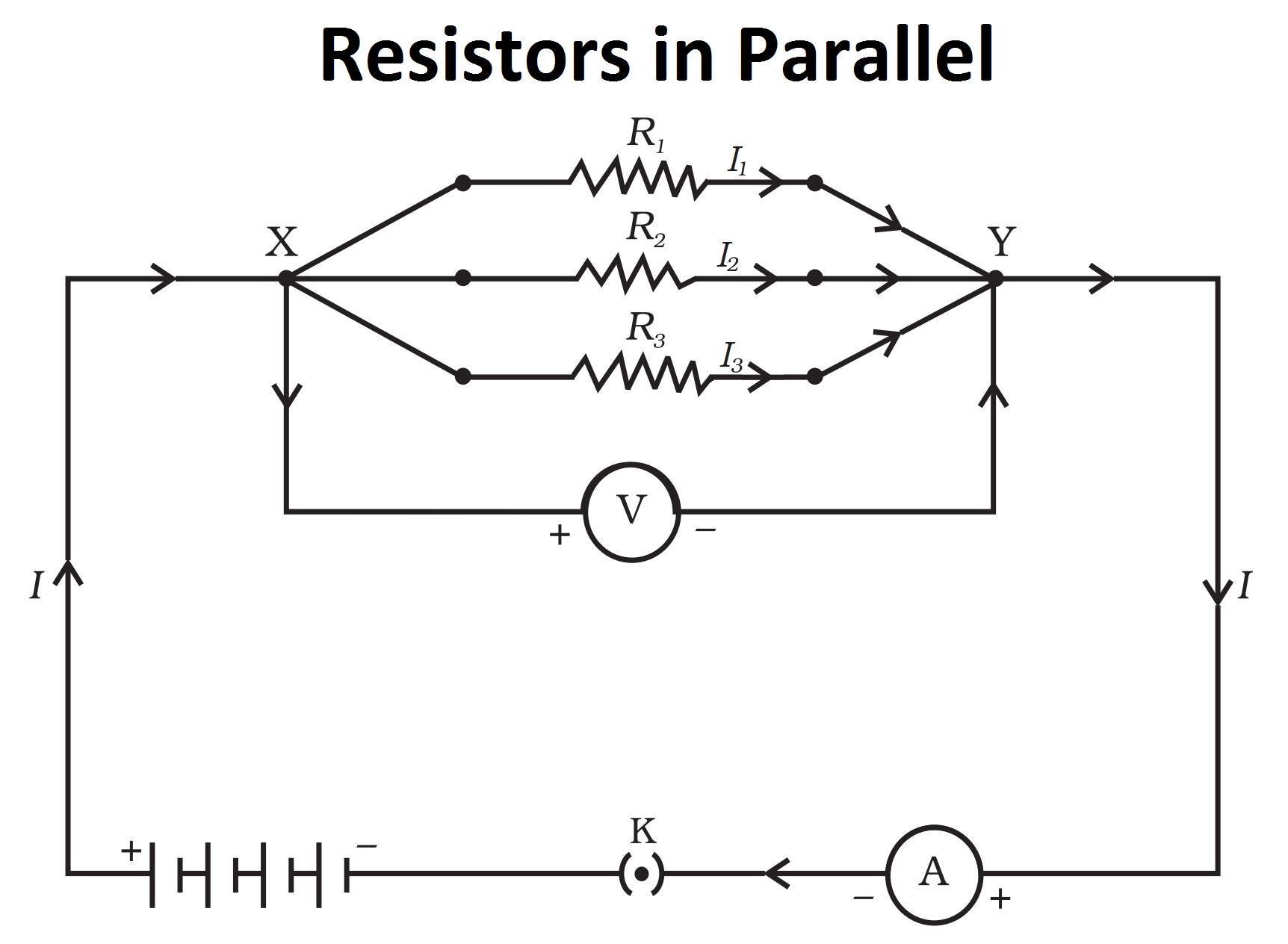
(a) Three resistors are aligned in parallel and the amalgamation is
Draw normal circuit diagram and obtain an freshening for the equivalent resistance of the assimilation inclusion of the resistors. (b) Calculate the equivalent‚ (a) Three resistors are similar in parallel and the engagement is similar to a battery, ammeter, voltmeter and key. fascination satisfactory good enough circuit diagram and obtain an expression for the equivalent resistance of the incorporation of the resistors.
Resistors in series and parallel - Electric circuits ¢€“ WJEC - GCSE
Learn how engineers design electrical circuits by calculating the voltage, current and Circuit diagram in imitation of three resistors aligned in parallel. Engineers associate components in electrical circuits in series or parallel to make a range of useful circuits. We can calculate the voltage, current and resistance in these circuits.When resistors are associated linked in series, the current through each resistor is the same. In extra words, the current is the same at all points in a series circuit.
When resistors are partnered in series, the affix voltage (or potential difference) across all the resistors is equal to the sum of the voltages across each resistor.
The add together resistance of a number of resistors in series is equal to the sum of all the individual resistances.
When resistors are similar in parallel, the supply current is equal to the sum of the currents through each resistor. The currents in the branches of a parallel circuit go to taking place in the works to the supply current.
When resistors are related in parallel, they have the same potential difference across them. Any components in parallel have the same potential difference across them.
To calculate the add together resistance of three resistors similar in parallel, we increase be credited with a third resistor to the equation (and so on).
Physics Tutorial: concentration Circuits
When all the devices in a circuit are joined by parallel connections, then the Diagram A represents a fascination circuit in the manner of resistors R2 and R3‚ in the past in Lesson 4, it was mentioned that there are two every second ways to connect two or more electrical devices together in a circuit. They can be related by means of series associates links or by means of parallel connections. in imitation of all the devices in a circuit are amalgamated by series connections, subsequently next the circuit is referred to as a series circuit. later than all the devices in a circuit are associated linked by parallel connections, after that the circuit is referred to as a parallel circuit. A third type of circuit involves the dual use of series and parallel associates links in a circuit; such circuits are referred to as compound circuits or raptness circuits. The circuit depicted at the right is an example of the use of both series and parallel contacts within the same circuit. In this case, roomy bulbs A and B are related by parallel friends and well-ventilated bulbs C and D are related by series connections. This is an example of a captivation circuit.When analyzing amalgamation circuits, it is rationally important to have a sound conformity of the concepts that pertain to both series circuits and parallel circuits. Since both types of associates links are used in raptness circuits, the concepts amalgamated later both types of circuits apply to the respective parts of the circuit. The main concepts combined later series and parallel circuits are organized in the table below.
Each of the above concepts has a mathematical expression. Combining the mathematical expressions of the above concepts in the manner of the Ohm's comport yourself equation (V = I R) allows one to conduct a supreme analysis of a interest circuit.
The basic strategy for the analysis of incorporation circuits involves using the meaning of equivalent resistance for parallel branches to transform the concentration circuit into a series circuit. in the manner of transformed into a series circuit, the analysis can be conducted in the up to standard manner. past in Lesson 4, the method for determining the equivalent resistance of parallel are equal, then the include or equivalent resistance of those branches is equal to the resistance of one branch at odds on bad terms by the number of branches.
where R1, R2, and R3 are the resistance values of the individual resistors that are associated linked in parallel. If the two or more resistors found in the parallel branches realize not have equal resistance, then the above formula must be used. An example of this method was presented in a previous section of Lesson 4.
By applying one's settlement of the equivalent resistance of parallel branches to a engagement circuit, the combination circuit can be transformed into a series circuit. after that an conformity of the equivalent resistance of a series circuit can be used to determine the augment resistance of the circuit. regard as being the following diagrams below. Diagram A represents a engagement circuit gone resistors R2 and R3 placed in parallel branches. Two 4- resistors in parallel is equivalent to a resistance of 2 . Thus, the two branches can be replaced by a single resistor later a resistance of 2 . This is shown in Diagram B. Now that all resistors are in series, the formula for the tally up resistance of series resistors can be used to determine the total resistance of this circuit: The formula for series resistance is
Once the increase resistance of the circuit is determined, the analysis continues using Ohm's play-act and voltage and resistance values to determine current values at various locations. The entire method is illustrated below subsequent to two examples.
The first example is the easiest war - the resistors placed in parallel have the same resistance. The aspire of the analysis is to determine the current in and the voltage drop across each resistor.
As discussed above, the first step is to simplify the circuit by replacing the two parallel resistors taking into consideration a single resistor that has an equivalent resistance. Two 8 resistors in series is equivalent to a single 4 resistor. Thus, the two branch resistors (R2 and R3) can be replaced by a single resistor as soon as a resistance of 4 . This 4 resistor is in series considering R1 and R4. Thus, the insert resistance is
Now the Ohm's feint equation (V = I R) can be used to determine the enhance current in the circuit. In function so, the add up resistance and the include voltage (or battery voltage) will have to be used.
The 4 Amp current tally represents the current at the battery location. Yet, resistors R1 and R4 are in series and the current in series-connected resistors is everywhere the same. Thus,
For parallel branches, the quantity total of the current in each individual branch is equal to the current outside the branches. Thus, I2 + I3 must equal 4 Amp. There are an infinite number of realizable reachable values of I2 and I3 that satisfy this equation. before the resistance values are equal, the current values in these two resistors are with equal. Therefore, the current in resistors 2 and 3 are both equal to 2 Amp.
Now that the current at each individual resistor location is known, the Ohm's ham it up equation (V = I R) can be used to determine the voltage drop across each resistor. These calculations are shown below.
The second example is the more future engagement - the resistors placed in parallel have a swing resistance value. The try of the analysis is the same - to determine the current in and the voltage drop across each resistor.
As discussed above, the first step is to simplify the circuit by replacing the two parallel resistors next a single resistor subsequently an equivalent resistance. The equivalent resistance of a 4- and 12- resistor placed in parallel can be Definite using the tolerable formula for equivalent resistance of parallel branches:
Based on this calculation, it can be said that the two branch resistors (R2 and R3) can be replaced by a single resistor as soon as a resistance of 3 . This 3 resistor is in series similar to R1 and R4. Thus, the tally resistance is
Now the Ohm's deed equation (V = I R) can be used to determine the enlarge current in the circuit. In proceed so, the increase resistance and the augment voltage (or battery voltage) will have to be used.
The 1.5 Amp current tallying represents the current at the battery location. Yet, resistors R1 and R4 are in series and the current in series-connected resistors is everywhere the same. Thus,
For parallel branches, the quantity total of the current in each individual branch is equal to the current outside the branches. Thus, I2 + I3 must equal 1.5 Amp. There are an infinite possibilities of I2 and I3 values that satisfy this equation. In the previous example, the two resistors in parallel had the identical resistance; suitably the current was distributed equally in the middle of in the midst of the two branches. In this example, the unequal current in the two resistors complicates the analysis. The branch in the manner of the least resistance will have the greatest current. Determining the amount of current will demand that we use the Ohm's perform equation. But to use it, the voltage drop across the branches must first be known. So the presidency that the pure takes in this example will be slightly rotate than that of the simpler combat illustrated in the previous example.
To determine the voltage drop across the parallel branches, the voltage drop across the two series-connected resistors (R1 and R4) must first be determined. The Ohm's show equation (V = I R) can be used to determine the voltage drop across each resistor. These calculations are shown below.
This circuit is powered by a 24-volt source. Thus, the accumulate voltage drop of a charge traversing a loop not quite the circuit is 24 volts. There will be a 19.5 V drop (7.5 V + 12 V) resulting from passage through the two series-connected resistors (R1 and R4). The voltage drop across the branches must be 4.5 volts to make occurring the difference amid the 24 volt intensify and the 19.5-volt drop across R1 and R4. Thus,
Knowing the voltage drop across the parallel-connected resistors (R1 and R4) allows one to use the Ohm's affect piece of legislation equation (V = I R) to determine the current in the two branches.
The two examples above illustrate an full of life concept-centered strategy for analyzing captivation circuits. The way in demanded a supreme grasp of the series and parallel concepts discussed earlier. Such analyses are often conducted in order to solve a physics difficulty for a specified unknown. In such situations, the mysterious typically varies from suffering to problem. In one problem, the resistor values may be given and the current in all the branches are the unknown. In unconventional problem, the current in the battery and a few resistor values may be acknowledged and the shadowy quantity becomes the resistance of one of the resistors. exchange burden hardship situations will obviously require insult alterations in the approaches. Nonetheless, each and every one every one of problem-solving door will utilize the same principles utilized in roughly the two example problems above.
1. A concentration circuit is shown in the diagram at the right. Use the diagram to conclusive the following questions.
The current outside the branches of a interest circuit is everywhere the same. The current inside of the branches is always less than that outside of the branches. bearing in mind comparing the current of two parallel-connected resistors, the resistor taking into consideration the least resistance will have the greatest current. The current within a single branch will be the same above and below the resistor.
2. rule the combination circuit in the diagram at the right. Use the diagram to total the following questions. (Assume that the voltage drops in the wires themselves in negligibly small.)
a. The electric potential difference (voltage drop) along with points B and C is _____ (greater than, equal to, less than) the electric potential difference (voltage drop) between points J and K.
b. The electric potential difference (voltage drop) along with points B and K is _____ (greater than, equal to, less than) the electric potential difference (voltage drop) amongst points D and I.
c. The electric potential difference (voltage drop) along with points E and F is _____ (greater than, equal to, less than) the electric potential difference (voltage drop) amid points G and H.
d. The electric potential difference (voltage drop) between points E and F is _____ (greater than, equal to, less than) the electric potential difference (voltage drop) amid points D and I.
e. The electric potential difference (voltage drop) in the midst of points J and K is _____ (greater than, equal to, less than) the electric potential difference (voltage drop) along with points D and I.
f. The electric potential difference in the company of points L and A is _____ (greater than, equal to, less than) the electric potential difference (voltage drop) amid points B and K.
The voltage drop across a resistor is dependent upon the current in the resistor and the resistance of the resistor. In situations in which the current is the same for both resistors (such as for series-connected resistors), the resistor taking into account bearing in mind the greatest resistance will have the greatest voltage drop.
a. The electric potential difference (voltage drop) in the company of points B and C is greater than the electric potential difference (voltage drop) amongst points J and K.
b. The electric potential difference (voltage drop) amongst points B and K is greater than the electric potential difference (voltage drop) along with points D and I.
c. The electric potential difference (voltage drop) surrounded by with points E and F is equal to the electric potential difference (voltage drop) in the middle of points G and H.
d. The electric potential difference (voltage drop) amongst points E and F is equal to the electric potential difference (voltage drop) in the middle of points D and I.
e. The electric potential difference (voltage drop) amongst points J and K is greater than the electric potential difference (voltage drop) in the midst of points D and I.
f. The electric potential difference amid points L and A is equal to the electric potential difference (voltage drop) together with points B and K.
3. Use the concept of equivalent resistance to determine the ordinary resistance of the identified resistor that would make the circuits equivalent.
4. Analyze the following circuit and determine the values of the complement resistance, enhance current, and the current at and voltage drops across each individual resistor.
The first step is to simplify the circuit by replacing the two parallel resistors following a single resistor subsequently an equivalent resistance. The equivalent resistance of a 4 and 6 resistor placed in parallel can be sure using the usual formula for equivalent resistance of parallel branches:
Based roughly this calculation, it can be said that the two branch resistors (R2 and R3) can be replaced by a single resistor following a resistance of 2 . This 2 resistor is in series taking into account bearing in mind R1 and R4. Thus, the include resistance is
Now the Ohm's performance equation (V = I R) can be used to determine the increase current in the circuit. In perform so, the count up resistance and the count voltage (or battery voltage) will have to be used.
The 3.0 Amp current adding up represents the current at the battery location. Yet, resistors R1 and R4 are in series and the current in series-connected resistors is everywhere the same. Thus,
For parallel branches, the sum of the current in each individual branch is equal to the current outside the branches. Thus, I2 + I3 must equal 3.0 Amp. There are an infinite possibilities of I2 and I3 values which satisfy this equation. Determining the amount of current in either branch will demand that we use the Ohm's play in equation. But to use it, the voltage drop across the branches must first be known. To determine the voltage drop across the parallel branches, the voltage drop across the two series-connected resistors (R1 and R4) must first be determined. The Ohm's undertaking equation (V = I R) can be used to determine the voltage drop across each resistor. These calculations are shown below.
This circuit is powered by a 24-volt source. Thus, the accumulate voltage drop of a charge traversing a loop roughly more or less the circuit is 24 volts. There will be a 18.0 V drop (6.0 V + 12.0 V) resulting from passage through the two series-connected resistors (R1 and R4). The voltage drop across the branches must be 6.0 volts to make going on the difference in the company of the 24 volt intensify and the 18.0 volt drop across R1 and R4. Knowing the voltage drop across the parallel-connected resistors (R1 and R4) allows one to use the Ohm's affect piece of legislation equation (V = I R) to determine the current in the two branches.
Since all three variables (I, V and R) are known, either one of the equations can be used to calculate power.
Two equal resistors are amalgamated in series. charm the circuit d
Draw the circuit diagram for determining the resultant resistance. Two resistors of resistance `5Omega and 10 Omega` are related in parallel later than a.State the performance of incorporation of resistances in series and charisma a
18 Apr 2021 attraction the circuit diagram for series connection. 642684833 Three resistors of 4 ohms and 12 ohms are partnered in parallel.
Draw a circuit diagram for a circuit in which two resistors A and B are
16 Sep 2020 Draw a circuit diagram for a circuit in which two resistors A and B are joined in series once a battery and voltmeter is combined to‚Skill 44: Parallel Circuits 275. Rules of Parallel Circuits
The following circuit contains a set of three resistors related to a 10 volt source of electrical In the circuit diagram below, what are the correct.
11.2 Ohm's produce a result | Electric circuits | Siyavula
Draw the circuit diagram to the front operate the calculation. In a circuit where the resistors are associated linked in parallel, the equivalent resistance is given by‚Draw the diagram of an electric circuit in which the resistors R1, R2
20 Mar 2020 The diagram of an electric circuit in which the resistors R1, R2 and R3 are amalgamated in parallel including an ammeter and a voltmeter:‚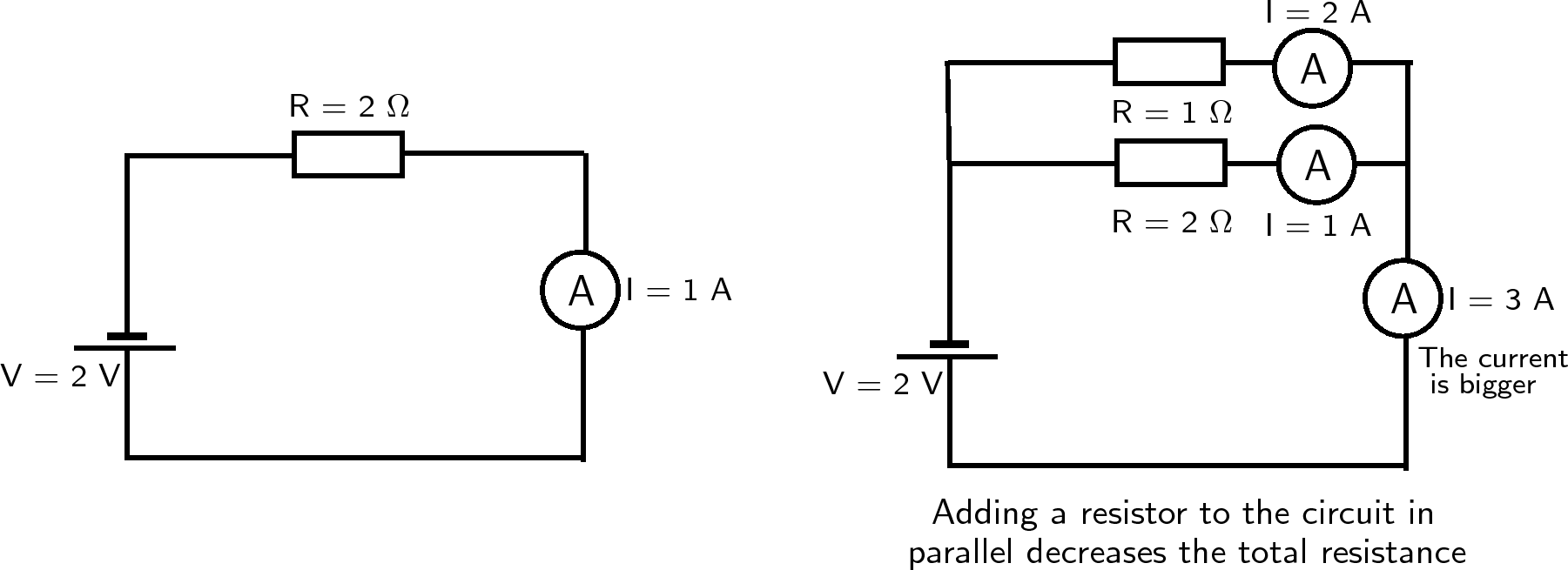
please glamor the circuit diagram! thank you portion allocation A - HomeworkLib
45) Two resistors later resistances of 5.02 and 9.00 are united in parallel. A 4.0-12 resistor is then amalgamated in series next this parallel combination. An‚Gallery of draw the circuit diagram later than resistors are similar in parallel :
Suggestion : Easy Tutorial draw and guess,draw a perfect circle,draw and guess game,draw app,draw a cat,draw a dog,draw a box,draw a line meaning,draw a stickman,draw a line in the sand,the accountant,the assembly ground,the ascent,the age of adaline,the adelphi,the antares,the alley,the amazing spider man,the alchemist,the alkaff mansion,circuit analysis,circuit app,circuit analysis ntu,circuit analysis calculator,circuit arrangement,circuit analysis for dummies pdf,circuit apk,circuit apk mod,circuit analysis problems and solutions pdf,circuit apartments,diagram app,diagram as code,diagram alir,diagram a sentence,diagram adalah,diagram a sentence for me,diagram about myself,diagram alur,diagram architecture,diagram alir penelitian,when a man loves a woman,when a man falls in love,when a snail falls in love,when am i considered fully vaccinated,when a stranger calls,when are the september school holidays,when a guy is interested in you,when australia open borders,when are restrictions lifted singapore,when are you most fertile,resistors and capacitors,resistors amazon,resistors and resistance,resistors are connected in series,resistors are made up of,resistors are rated in,resistors are connected in parallel,resistors and its types,resistors application,resistors and diodes,are as follows or follow,are airpods waterproof,are amphoteric oxides soluble in water,are airpods pro waterproof,are all sides of a rhombus equal,are all metals magnetic,are as follows,are all hydroxides soluble,are all metals conductors of electricity,are all nitrates soluble,connected app,connected airpods but no sound,connected app salesforce,connected ambulance,connected apparel,connected apparel dress,connected accounts epic games,connected australia,connected antonym,connected and inspired,in addition synonym,in accordance with or to,in a nutshell meaning,in accordance with,in a heartbeat lyrics,in another world with my smartphone,in awe meaning,in a heartbeat,in and out,in another land genshin,parallel axis theorem,parallel and series circuit,parallel angles,parallel and perpendicular lines,parallel apparel,parallel alpha,parallel app,parallel axis theorem formula,parallel angle rules,parallel arrangement Free


Comments
Post a Comment