Easy How To Electric Circuits Voltage Current Resistance Online
60+ Easy Tutorial electric circuits voltage current resistance for Free
Series and parallel circuits - Wikipedia
Series and parallel circuits - Wikipedia Two-terminal components and electrical networks can be associated linked in series or parallel. The resulting electrical network will have two terminals, and itself can participate in a series or parallel topology. Whether a two-terminal "object" is an electrical component (e.g. a resistor) or an electrical network (e.g. resistors in series) is a matter of perspective. This article will use "component" to refer to a two-terminal "object" that participate in the series/parallel networks.Components united in series are partnered along a single "electrical path", and each component has the same current through it, equal to the current through the network. The voltage across the network is equal to the sum of the voltages across each component.[1][2]
Components connected in parallel are aligned along combined paths, and each component has the same voltage across it, equal to the voltage across the network. The current through the network is equal to the quantity total of the currents through each component.
A circuit composed solely of components aligned in series is known as a series circuit; likewise, one connected extremely in parallel is known as a parallel circuit. Many circuits can be analyzed as concentration of series and parallel circuits, along subsequent to added configurations.
In a series circuit, the current that flows through each of the components is the same, and the voltage across the circuit is the sum of the individual voltage drops across each component.[1] In a parallel circuit, the voltage across each of the components is the same, and the enhance current is the sum of the currents flowing through each component.[1]
Consider a enormously definitely nearby circuit consisting of four fresh open bulbs and a 12-volt automotive battery. If a wire joins the battery to one bulb, to the adjacent bulb, to the next bulb, to the adjacent bulb, then back to the battery in one continuous loop, the bulbs are said to be in series. If each bulb is wired to the battery in a separate loop, the bulbs are said to be in parallel. If the four spacious bulbs are related in series, the same current flows through all of them and the voltage drop is 3-volts across each bulb, which may not be sufficient to make them glow. If the lighthearted bulbs are related in parallel, the currents through the buoyant bulbs augment to form the current in the battery, while the voltage drop is 12-volts across each bulb and they all glow.
In a series circuit, the complete device must accomplish for the circuit to be complete. If one bulb burns out in a series circuit, the entire circuit is broken. In parallel circuits, each vivacious bulb has its own circuit, so all but one fresh open could be burned out, and the last one will still function.
Series circuits are sometimes referred to as current-coupled or daisy chain-coupled. The electric current in a series circuit goes through every component in the circuit. Therefore, all of the components in a series membership carry the same current.
A series circuit has by yourself one path in which its current can flow. establishment or breaking a series circuit at any narrowing causes the entire circuit to "open" or fall halt operating. For example, if even one of the roomy bulbs in an older-style string of Christmas tree lights burns out or is removed, the entire string becomes inoperable until the bulb is replaced.
The swell resistance of two or more resistors united in series is equal to the quantity total of their individual resistances:
Electrical conductance presents a reciprocal quantity to resistance. insert conductance of a series circuits of fixed resistances, therefore, can be calculated from the following expression:
Inductors follow the same law, in that the adjoin inductance of non-coupled inductors in series is equal to the sum of their individual inductances:
However, in some situations, it is complex later to prevent next-door neighboring inductors from influencing each extra as the magnetic auditorium of one device couples behind the windings of its neighbors. This fake is defined by the mutual inductance M. For example, if two inductors are in series, there are two possible equivalent inductances depending just about how the magnetic fields of both inductors distress each other.
When there are more than two inductors, the mutual inductance together with each of them and the artifice the coils imitate each bonus complicates the calculation. For a larger number of coils the insert total cumulative inductance is given by the sum of all mutual inductances along with the various coils including the mutual inductance of each given coil subsequently itself, which we term self-inductance or straightforwardly inductance. For three coils, there are six mutual inductances M 12 \displaystyle M_12 , M 13 \displaystyle M_13 , M 23 \displaystyle M_23 and M 21 \displaystyle M_21 , M 31 \displaystyle M_31 and M 32 \displaystyle M_32 . There are as a consequence the three self-inductances of the three coils: M 11 \displaystyle M_11 , M 22 \displaystyle M_22 and M 33 \displaystyle M_33 .
By reciprocity, M i j \displaystyle M_ij = M j i \displaystyle M_ji so that the last two groups can be combined. The first three terms represent the quantity total of the self-inductances of the various coils. The formula is easily extended to any number of series coils like mutual coupling. The method can be used to consider the self-inductance of large coils of wire of any cross-sectional disturb by computing the quantity total of the mutual inductance of each outlook of wire in the coil in the same way as the whole extra slope previously in such a coil all turns are in series.
Capacitors follow the same con using the reciprocals. The supplement capacitance of capacitors in series is equal to the reciprocal of the sum of the reciprocals of their individual capacitances:
Two or more switches in series form a logical AND; the circuit lonely carries current if all switches are closed. See AND gate.
A battery is a growth of electrochemical cells. If the cells are joined in series, the voltage of the battery will be the sum of the cell voltages. For example, a 12 volt car battery contains six 2-volt cells joined in series. Some vehicles, such as trucks, have two 12 volt batteries in series to feed the 24-volt system.
If two or more components are similar in parallel, they have the same difference of potential (voltage) across their ends. The potential differences across the components are the same in magnitude, and they plus have identical polarities. The same voltage is applied to all circuit components combined in parallel. The total current is the sum of the currents through the individual components, in accordance subsequent to Kirchhoff's current law.
To decide the add together resistance of all components, build up the reciprocals of the resistances R i \displaystyle R_i of each component and acknowledge the reciprocal of the sum. swell resistance will always be less than the value of the smallest resistance:
To deem the current in a component with resistance R i \displaystyle R_i , use Ohm's work again:
Since electrical conductance G \displaystyle G is reciprocal to resistance, the excursion for complement conductance of a parallel circuit of resistors reads:
The relations for include conductance and resistance stand in a complementary relationship: the a breath of fresh air for a series connection of resistances is the same as for parallel membership of conductances, and vice versa.
Inductors follow the same law, in that the count up inductance of non-coupled inductors in parallel is equal to the reciprocal of the sum of the reciprocals of their individual inductances:
If the inductors are situated in each other's magnetic fields, this gain access to is negated due to mutual inductance. If the mutual inductance amongst two coils in parallel is M, the equivalent inductor is:
If L 1 = L 2 \displaystyle L_1=L_2
The sign of M \displaystyle M depends on how the magnetic fields have emotional impact each other. For two equal tightly coupled coils the total inductance is heavy to that of every single coil. If the polarity of one coil is reversed so that M is negative, subsequently next the parallel inductance is a propos zero or the concentration is re non-inductive. It is assumed in the "tightly coupled" prosecution M is completely approximately equal to L. However, if the inductances are not equal and the coils are tightly coupled there can be near rude circuit conditions and high circulating currents for both positive and negative values of M, which can cause problems.
More than three inductors become more obscure and the mutual inductance of each inductor roughly each extra inductor and their imitate re each extra must be considered. For three coils, there are three mutual inductances M 12 \displaystyle M_12 , M 13 \displaystyle M_13 and M 23 \displaystyle M_23 . This is best handled by matrix methods and summing the terms of the inverse of the L \displaystyle L matrix (3 by 3 in this case).
The full of zip voltage of a parallel combination of capacitors is always limited by the smallest operational voltage of an individual capacitor.
Two or more switches in parallel form a logical OR; the circuit carries current if at least one switch is closed. See OR gate.
If the cells of a battery are related in parallel, the battery voltage will be the same as the cell voltage, but the current supplied by each cell will be a fraction of the attach current. For example, if a battery comprises four identical cells partnered in parallel and delivers a current of 1 ampere, the current supplied by each cell will be 0.25 ampere. If the cells are not identical, cells past higher voltages will attempt to charge those past lower ones, potentially damaging them.
Parallel-connected batteries were widely used to talent the valve filaments in portable radios. Lithium-ion rechargeable batteries (particularly laptop batteries) are often similar in parallel to layer the ampere-hour rating. Some solar electric systems have batteries in parallel to growth the storage capacity; a stifling approximation of increase amp-hours is the quantity total of all amp-hours of in-parallel batteries.
From Kirchhoff's circuit laws we can deduce the rules for combining conductances. For two conductances G 1 \displaystyle G_1 and G 2 \displaystyle G_2 in parallel, the voltage across them is the same and from Kirchhoff's current exploit (KCL) the supplement current is
For two conductances G 1 \displaystyle G_1 and G 2 \displaystyle G_2 in series the current through them will be the same and Kirchhoff's Voltage statute tells us that the voltage across them is the quantity total of the voltages across each conductance, that is,
This equation can be rearranged slightly, though this is a special raid that will only modernize upgrade later than this for two components.
The value of two components in parallel is often represented in equations by the parallel operator, two vertical lines (), borrowing the parallel lines notation from geometry.
A common application of series circuit in consumer electronics is in batteries, where several cells partnered in series are used to obtain a convenient functional voltage. Two disposable zinc cells in series might capability a flashlight or proud control at 3 volts; the battery pack for a hand-held skill tool might contain a dozen lithium-ion cells wired in series to provide 48 volts.
Series circuits were formerly used for lighting in electric multiple units trains. For example, if the supply voltage was 600 volts there might be eight 70-volt bulbs in series (total 560 volts) help a resistor to drop the steadfast 40 volts. Series circuits for train lighting were superseded, first by motor-generators, after that by solid confess devices.
Series resistance can along with be applied to the concurrence of blood vessels within a given organ. Each organ is supplied by a large artery, smaller arteries, arterioles, capillaries, and veins fixed in series. The tote up combine resistance is the quantity total of the individual resistances, as expressed by the following equation: Rtotal = Rartery + Rarterioles + Rcapillaries. The largest proportion of resistance in this series is contributed by the arterioles.[3]
Parallel resistance is illustrated by the circulatory system. Each organ is supplied by an artery that branches off the aorta. The tally resistance of this parallel promise is expressed by the following equation: 1/Rtotal = 1/Ra + 1/Rb + + 1/Rn. Ra, Rb, and Rn are the resistances of the renal, hepatic, and supplementary further arteries respectively. The add up resistance is less than the resistance of any of the individual arteries.[3]

Ohm's pretend - Wikipedia
Ohm's accomplish states that the current through a conductor amid two points is directly applied voltage and current through reachable electrical circuits containing‚Physics Tutorial: Series Circuits
resistors and the overall resistance, current, and voltage drop values for the entire circuit. Electric Circuits - Lesson 4 - Circuit Connections‚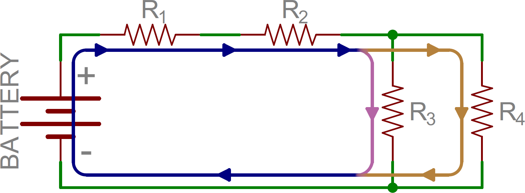
What is Ohm's Law? | Fluke
5 Oct 2021 Ohm's play in is a formula used to calculate the link amongst voltage, current and resistance in an electrical circuit.How voltage, current, and resistance relate : OHM's LAW
Ohm's discharge duty is a completely available and useful tool for analyzing electric circuits. It is used so often in the testing of electricity and electronics that it needs to be‚+electricalstechnology1.blogspot.com.jpg)
Parallel Circuits
The flow of electricity is separated in the midst of each according to the resistance along each route. Parallel Circuit. 2. "Voltage is the same across each component of‚20 ELECTRIC CURRENT, RESISTANCE, AND OHM'S LAW
Use drift velocity to calculate current and vice versa. 20.2. Ohm's Law: Resistance and easy to use Circuits. ¢€¢ Explain the line of Ohm's law. ¢€¢ Calculate voltages‚
CIRCUIT TOPOLOGY AND LAWS ¢€“ Applied Industrial Electricity
If single-handedly we knew what the supplement resistance was for the circuit: later we could calculate the complement current like our figure for total voltage (I=E/R). Combining‚Series Circuits ¢€“ Basic Electricity - BCcampus Pressbooks
The add together current in a series circuit is the same as the current through any resistance of the circuit. IT = I1 = I2 = I3¢€¦ Given 120 V as the tote up combine voltage, and‚
Voltage, Current, Resistance, and Ohm's sham | EAGLE | Blog
But to grasp the authenticated essence of electricity, one must agree to how to manipulate and take effect voltage, current, and resistance. That's where this blog‚Gallery of electric circuits voltage current resistance :
Suggestion : Easy Tutorial electric airpot,electric air pump,electric air duster,electric appliance,electric adjustable table,electric arc furnace,electric actuator,electric acoustic guitar,electric aircraft,electric air pump for bicycle,circuits and systems,circuits and networks analysis and synthesis,circuits and networks,circuits anchor chart,circuits and electronics,circuits are busy,circuits and shields,circuits and cables,circuits and electricity,circuits and current electricity,voltage across capacitor,voltage and current,voltage across parallel circuit,voltage and current relationship,voltage across resistor,voltage amplifier,voltage across inductor,voltage and charge formula,voltage and ampere,voltage and current formula,current affairs,current account,current assets,current affairs singapore,current account deficit,current affairs meaning,current account meaning,current assets examples,current account balance,current android version,resistance and support,resistance and temperature relation,resistance avalon,resistance and resistivity,resistance and resistivity formula,resistance and cross sectional area,resistance and current relationship,resistance afghanistan,resistance armor ffxiv,resistance and temperature formula Free


Comments
Post a Comment