Tutorial 1.draw Circuit Diagram Of Parallel Resonance Circuit Online
45+ Tutorial 1.draw circuit diagram of parallel resonance circuit Online
Single-phase AC Circuits - NPTEL
phase ac supply, and after that charisma unchangeable phasor diagram? resonance conditions in series and parallel circuits are presented in detail, along considering the.
RLC circuit - Wikipedia
This occurs because the impedances of the inductor and capacitor at resonance are equal but of opposite sign and cancel out. Circuits where L‚ An RLC circuit is an electrical circuit consisting of a resistor (R), an inductor (L), and a capacitor (C), partnered in series or in parallel. The declare of the circuit is derived from the letters that are used to denote the constituent components of this circuit, where the sequence of the components may vary from RLC.The circuit forms a harmonic oscillator for current, and resonates in a similar way as an LC circuit. Introducing the resistor increases the decay of these oscillations, which is with known as damping. The resistor along with reduces the peak resonant frequency. In ordinary conditions, some resistance is unavoidable even if a resistor is not specifically included as a component; an ideal, pure LC circuit exists isolated in the domain of superconductivity, a swine bodily effect demonstrated to this narrowing by yourself at temperatures far below and/or pressures far above what are found naturally anywhere a propos the Earth's surface.
RLC circuits have many applications as oscillator circuits. Radio receivers and television sets use them for tuning to select a narrow frequency range from ambient radio waves. In this role, the circuit is often referred to as a tuned circuit. An RLC circuit can be used as a band-pass filter, band-stop filter, low-pass filter or high-pass filter. The tuning application, for instance, is an example of band-pass filtering. The RLC filter is described as a second-order circuit, meaning that any voltage or current in the circuit can be described by a second-order differential equation in circuit analysis.
The three circuit elements, R, L and C, can be collect in a number of alternative topologies. All three elements in series or all three elements in parallel are the simplest in concept and the most welcoming to analyse. There are, however, added arrangements, some in imitation of practical importance in real circuits. One matter concern often encountered is the dependence obsession to understand into account inductor resistance. Inductors are typically constructed from coils of wire, the resistance of which is not usually desirable, but it often has a significant effect vis-а-vis the circuit.
An important property of this circuit is its realization to resonate at a specific frequency, the resonance frequency, f0. Frequencies are measured in units of hertz. In this article, angular frequency, 0, is used because it is more mathematically convenient. This is measured in radians per second. They are related to each other by a user-friendly proportion,
Resonance occurs because life for this concern is stored in two every other ways: in an electric pitch ring as the capacitor is charged and in a magnetic showground as current flows through the inductor. computer graphics can be transferred from one to the supplementary further within the circuit and this can be oscillatory. A mechanical analogy is a weight suspended regarding a spring which will oscillate going on and down in the same way as released. This is no passing metaphor; a weight in this area a spring is described by exactly the same second order differential equation as an RLC circuit and for all the properties of the one system there will be found an analogous property of the other. The mechanical property answering to the resistor in the circuit is friction in the springweight system. Friction will slowly bring any oscillation to a fade away if there is no external force driving it. Likewise, the resistance in an RLC circuit will "damp" the oscillation, diminishing it in the same way as get older if there is no driving AC capability source in the circuit.
The resonance frequency is defined as the frequency at which the impedance of the circuit is at a minimum. Equivalently, it can be defined as the frequency at which the impedance is purely genuine (that is, purely resistive). This occurs because the impedances of the inductor and capacitor at resonance are equal but of opposite sign and cancel out. Circuits where L and C are in parallel rather than series actually have a maximum impedance rather than a minimum impedance. For this reason they are often described as antiresonators, it is still usual, however, to broadcast the frequency at which this occurs as the resonance frequency.
The resonance frequency is defined in terms of the impedance presented to a driving source. It is yet nevertheless practicable for the circuit to carry vis-а-vis oscillating (for a time) after the driving source has been removed or it is subjected to a step in voltage (including a step down to zero). This is same thesame to the pretentiousness that a tuning fork will carry regarding ringing after it has been struck, and the effect is often called ringing. This effect is the peak natural resonance frequency of the circuit and in general is not exactly the same as the driven resonance frequency, although the two will usually be quite close to each other. Various terms are used by different authors to distinguish the two, but resonance frequency conclusive usually means the driven resonance frequency. The driven frequency may be called the undamped resonance frequency or undamped natural frequency and the peak frequency may be called the damped resonance frequency or the damped natural frequency. The reason for this terminology is that the driven resonance frequency in a series or parallel resonant circuit has the value[1]
This is exactly the same as the resonance frequency of an LC circuit, that is, one considering no resistor present. The resonant frequency for an RLC circuit is the same as a circuit in which there is no damping, fittingly undamped resonance frequency. The peak resonance frequency, roughly the extra hand, depends regarding the value of the resistor and is described as the damped resonant frequency. A very damped circuit will fail to resonate at all similar to not driven. A circuit subsequently a value of resistor that causes it to be just on the order of the edge of ringing is called critically damped. Either side of systematically methodically damped are described as underdamped (ringing happens) and overdamped (ringing is suppressed).
Circuits gone topologies more mysterious than within reach series or parallel (some examples described difficult far along in the article) have a driven resonance frequency that deviates from 0 = 1 / L C \displaystyle \omega _0=1/\sqrt L\,C~ , and for those the undamped resonance frequency, damped resonance frequency and driven resonance frequency can all be different.
Damping is caused by the resistance in the circuit. It determines whether or not the circuit will resonate naturally (that is, without a driving source). Circuits that will resonate in this way are described as underdamped and those that will not are overdamped. Damping attenuation (symbol ) is measured in nepers per second. However, the unitless damping factor (symbol , zeta) is often a more useful measure, which is related to by
The special dogfight of = 1 is called critical damping and represents the case of a circuit that is just roughly the border of oscillation. It is the minimum damping that can be applied without causing oscillation.
The resonance effect can be used for filtering, the sudden regulate in impedance near resonance can be used to pass or block signals stifling to the resonance frequency. Both band-pass and band-stop filters can be constructed and some filter circuits are shown difficult far along in the article. A key parameter in filter design is bandwidth. The bandwidth is measured in the midst of the cutoff frequencies, most frequently defined as the frequencies at which the aptitude passed through the circuit has fallen to half the value passed at resonance. There are two of these half-power frequencies, one above, and one below the resonance frequency
where is the bandwidth, 1 is the lower half-power frequency and 2 is the upper half-power frequency. The bandwidth is related to attenuation by
where the units are radians per second and nepers per second respectively.[citation needed] added units may require a conversion factor. A more general proceed of bandwidth is the fractional bandwidth, which expresses the bandwidth as a fraction of the resonance frequency and is given by
The fractional bandwidth is with often avowed confirmed as a percentage. The damping of filter circuits is adjusted to result in the required bandwidth. A narrow band filter, such as a notch filter, requires low damping. A wide band filter requires high damping.
The Q factor is a widespread acquit yourself used to characterise resonators. It is defined as the peak vigor stored in the circuit at odds on bad terms by the average life dissipated in it per radian at resonance. Low-Q circuits are therefore damped and lossy and high-Q circuits are underdamped. Q is related to bandwidth; low-Q circuits are wide-band and high-Q circuits are narrow-band. In fact, it happens that Q is the inverse of fractional bandwidth
The parameters , Fb, and Q are all scaled to 0. This means that circuits which have similar parameters share similar characteristics regardless of whether or not they are keen in the same frequency band.
The article next gives the analysis for the series RLC circuit in detail. supplementary further configurations are not described in such detail, but the key differences from the series fighting are given. The general form of the differential equations given in the series circuit section are applicable to all second order circuits and can be used to describe the voltage or current in any element of each circuit.
In this circuit, the three components are all in series when the voltage source. The governing differential equation can be found by substituting into Kirchhoff's voltage feat (KVL) the constitutive equation for each of the three elements. From the KVL,
where VR, VL and VC are the voltages across R, L and C respectively and V(t) is the time-varying voltage from the source.
Substituting V R = R I ( t ) \displaystyle V_R=RI(t) , V L = L d I ( t ) d t \displaystyle V_L=LdI(t) \over dt and V C = V ( 0 ) + 1 C 0 t I ( ) d \displaystyle V_C=V(0)+\frac 1C\int _0^tI(\tau )\,d\tau into the equation above yields:
For the fighting where the source is an perpetual voltage, taking the epoch derivative and dividing by L leads to the following second order differential equation:
and 0 are both in units of angular frequency. is called the neper frequency, or attenuation, and is a play a part of how fast the transient tribute reply of the circuit will die away after the stimulus has been removed. Neper occurs in the broadcast because the units can afterward be considered to be nepers per second, neper beast a unit of attenuation. 0 is the angular resonance frequency.[3]
A useful parameter is the damping factor, , which is defined as the ratio of these two; although, sometimes is referred to as the damping factor and is not used.[5]
The coefficients A1 and A2 are sure by the boundary conditions of the specific difficulty brute analysed. That is, they are set by the values of the currents and voltages in the circuit at the onset of the transient and the presumed value they will be of the same mind to after infinite time.[8] The differential equation for the circuit solves in three substitute substitute ways depending on the value of . These are overdamped ( > 1), underdamped ( < 1), and critically damped ( = 1).
The underdamped appreciation is a decaying oscillation at frequency d. The oscillation decays at a rate Definite by the attenuation . The exponential in describes the envelope of the oscillation. B1 and B2 (or B3 and the phase shift in the second form) are arbitrary constants certain by boundary conditions. The frequency d is given by[11]
This is called the damped resonance frequency or the damped natural frequency. It is the frequency the circuit will naturally swap at if not driven by an external source. The resonance frequency, 0, which is the frequency at which the circuit will resonate in the manner of driven by an external oscillation, may often be referred to as the undamped resonance frequency to distinguish it.[13]
The rationally damped confession represents the circuit tribute reply that decays in the fastest feasible epoch without going into oscillation. This consideration is important in control systems where it is required to reach the desired welcome as gruffly as practicable without overshooting. D1 and D2 are arbitrary constants determined by boundary conditions.[15]
The series RLC can be analyzed for both transient and steady AC state behavior using the Laplace transform.[16] If the voltage source above produces a waveform taking into account bearing in mind Laplace-transformed V(s) (where s is the obscure frequency s = + j), the KVL can be applied in the Laplace domain:
The poles of Y(s) are identical to the roots s1 and s2 of the characteristic polynomial of the differential equation in the section above.
Sinusoidal steady welcome is represented by letting s = j, where j is the imaginary unit. Taking the magnitude of the above equation like this substitution:
There is a peak value of |I(j)|. The value of at this peak is, in this particular case, equal to the undamped natural resonance frequency:[17]
From the frequency acceptance of the current, the frequency reaction of the voltages across the various circuit elements can with be determined.
The properties of the parallel RLC circuit can be obtained from the duality membership of electrical circuits and subsequent to that the parallel RLC is the dual impedance of a series RLC. Considering this, it becomes certain that the differential equations describing this circuit are identical to the general form of those describing a series RLC.
Likewise, the bonus scaled parameters, fractional bandwidth and Q are in addition to reciprocals of each other. This means that a wide-band, low-Q circuit in one topology will become a narrow-band, high-Q circuit in the bonus topology subsequently constructed from components gone identical values. The fractional bandwidth and Q of the parallel circuit are given by
The alter from a series bargain to a parallel understanding results in the circuit having a peak in impedance at resonance rather than a minimum, so the circuit is an anti-resonator.
The graph opposite shows that there is a minimum in the frequency nod of the current at the resonance frequency 0 = 1 / L C \displaystyle ~\omega _0=1/\sqrt \,L\,C~~ behind the circuit is driven by a constant voltage. just about the supplementary further hand, if driven by a constant current, there would be a maximum in the voltage which would follow the same curve as the current in the series circuit.
A series resistor subsequently the inductor in a parallel LC circuit as shown in Figure 4 is a topology commonly encountered where there is a compulsion to tolerate into account the resistance of the coil winding. Parallel LC circuits are frequently used for bandpass filtering and the Q is largely governed by this resistance. The resonant frequency of this circuit is[19]
This is the resonant frequency of the circuit defined as the frequency at which the gain access to has zero imaginary part. The frequency that appears in the generalised form of the characteristic equation (which is the same for this circuit as previously)
where QL = .mw-parser-output .sfracwhite-space:nowrap.mw-parser-output .sfrac.tion,.mw-parser-output .sfrac .tiondisplay:inline-block;vertical-align:-0.5em;font-size:85%;text-align:center.mw-parser-output .sfrac .num,.mw-parser-output .sfrac .dendisplay:block;line-height:1em;margin:0 0.1em.mw-parser-output .sfrac .denborder-top:1px solid.mw-parser-output .sr-onlyborder:0;clip:rect(0,0,0,0);height:1px;margin:-1px;overflow:hidden;padding:0;position:absolute;width:1px0L/R is the setting factor of the coil. This can be capably skillfully approximated by[21]
In the same vein, a resistor in parallel afterward the capacitor in a series LC circuit can be used to represent a capacitor later a lossy dielectric. This configuration is shown in Figure 5. The resonant frequency (frequency at which the impedance has zero imaginary part) in this feat is given by[22]
The first evidence that a capacitor could develop electrical oscillations was discovered in 1826 by French scientist Felix Savary.[23][24] He found that afterward a Leyden jar was discharged through a wire wound concerning an iron needle, sometimes the needle was left magnetized in one management running and sometimes in the opposite direction. He correctly deduced that this was caused by a damped oscillating exoneration current in the wire, which reversed the magnetization of the needle back and forth until it was too small to have an effect, leaving the needle magnetized in a random direction.
American physicist Joseph Henry repeated Savary's experiment in 1842 and came to the same conclusion, apparently independently.[25][26] British scientist William Thomson (Lord Kelvin) in 1853 showed mathematically that the discharge of a Leyden jar through an inductance should be oscillatory, and derived its resonant frequency.[23][25][26]
British radio speculative Oliver Lodge, by discharging a large battery of Leyden jars through a long wire, created a tuned circuit as soon as its resonant frequency in the audio range, which produced a musical melody from the spark considering it was discharged.[25] In 1857, German physicist Berend Wilhelm Feddersen photographed the spark produced by a resonant Leyden jar circuit in a rotating mirror, providing visible evidence of the oscillations.[23][25][26] In 1868, Scottish physicist James Clerk Maxwell calculated the effect of applying an different current to a circuit in the manner of inductance and capacitance, showing that the recognition is maximum at the resonant frequency.[23]
The first example of an electrical resonance curve was published in 1887 by German physicist Heinrich Hertz in his pioneering paper something like the discovery of radio waves, showing the length of spark obtainable from his spark-gap LC resonator detectors as a measure of frequency.[23]
One of the first demonstrations of resonance along with tuned circuits was Lodge's "syntonic jars" experiment vis-а-vis 1889[23][25] He placed two resonant circuits next-door to each other, each consisting of a Leyden jar joined to an malleable one-turn coil taking into consideration a spark gap. afterward a high voltage from an induction coil was applied to one tuned circuit, creating sparks and hence oscillating currents, sparks were excited in the supplementary further tuned circuit lonesome similar to the inductors were adjusted to resonance. Lodge and some English scientists preferred the term "syntony" for this effect, but the term "resonance" eventually stuck.[23]
The first practical use for RLC circuits was in the 1890s in spark-gap radio transmitters to allow the receiver to be tuned to the transmitter. The first patent for a radio system that allowed tuning was filed by Lodge in 1897, although the first practical systems were invented in 1900 by Anglo Italian radio fortune-hunter Guglielmo Marconi.[23]
A agreed frequent use of these circuits is in the tuning circuits of analogue radios. Adjustable tuning is commonly achieved with a parallel plate bendable capacitor which allows the value of C to be changed and express to stations roughly speaking rotate frequencies. For the IF stage in the radio where the tuning is preset in the factory, the more enjoyable unlimited is an flexible core in the inductor to accustom yourself L. In this design, the core (made of a high permeability material that has the effect of increasing inductance) is threaded so that it can be screwed supplementary new in, or screwed supplementary new out of the inductor winding as required.
In the filtering application, the resistor becomes the load that the filter is operational into. The value of the damping factor is chosen based roughly the desired bandwidth of the filter. For a wider bandwidth, a larger value of the damping factor is required (and vice versa). The three components meet the expense of offer the designer three degrees of freedom. Two of these are required to set the bandwidth and resonant frequency. The designer is yet nevertheless left in the manner of one which can be used to scale R, L and C to convenient practical values. Alternatively, R may be predetermined by the external circuitry which will use the last degree of freedom.
An RLC circuit can be used as a low-pass filter. The circuit configuration is shown in Figure 6. The corner frequency, that is, the frequency of the 3 dB point, is given by
A band-pass filter can be formed like an RLC circuit by either placing a series LC circuit in series past the load resistor or else by placing a parallel LC circuit in parallel past the load resistor. These arrangements are shown in Figures 8 and 9 respectively. The centre frequency is given by
The shunt savings account of the circuit is designed to be driven by a high impedance source, that is, a constant current source. numb those conditions the bandwidth is[29]
Figure 10 shows a band-stop filter formed by a series LC circuit in shunt across the load. Figure 11 is a band-stop filter formed by a parallel LC circuit in series past the load. The first war requires a high impedance source so that the current is diverted into the resonator considering it becomes low impedance at resonance. The second skirmish requires a low impedance source so that the voltage is dropped across the antiresonator in the same way as it becomes high impedance at resonance.[30]
For applications in oscillator circuits, it is generally desirable to make the attenuation (or equivalently, the damping factor) as small as possible. In practice, this strive for requires making the circuit's resistance R as small as physically possible for a series circuit, or alternatively increasing R to as much as doable for a parallel circuit. In either case, the RLC circuit becomes a courteous approximation to an ideal LC circuit. However, for very low-attenuation circuits (high Q-factor), issues such as dielectric losses of coils and capacitors can become important.
If R is small, consisting isolated of the inductor winding resistance say, after that this current will be large. It will drop a voltage across the inductor of
An equal magnitude voltage will in addition to be seen across the capacitor but in antiphase to the inductor. If R can be made sufficiently small, these voltages can be several times the input voltage. The voltage ratio is, in fact, the Q of the circuit,
A same thesame effect is observed taking into consideration currents in the parallel circuit. Even though the circuit appears as high impedance to the external source, there is a large current circulating in the internal loop of the parallel inductor and capacitor.
An overdamped series RLC circuit can be used as a pulse discharge circuit. Often it is useful to know the values of components that could be used to produce a waveform. This is described by the form
Such a circuit could consist of an activity storage capacitor, a load in the form of a resistance, some circuit inductance and a switch all in series. The initial conditions are that the capacitor is at voltage, V0, and there is no current flowing in the inductor. If the inductance L is known, then the long-lasting parameters are given by the following capacitance:
LC circuit - Wikipedia
An LC circuit, plus called a resonant circuit, tank circuit, or tuned circuit, is an electric circuit consisting of an inductor, represented by the letter L‚
Phasor Diagram - an overview | ScienceDirect Topics
which is identical to the resonance frequency for a series resonant circuit as given by (2.18). The door at resonance is fittingly Y = 1/R. At parallel‚Series parallel resonance circuit - SlideShare
10 Apr 2019 In parallel RLC circuits the voltage in two branches of circuit is same but current divides, appropriately resonant frequency is given by the‚
Parallel RLC Circuit: What is it? (Circuit Analysis) | Electrical4U
25 Oct 2020 In series RLC circuit, the current flowing through all the three components i.e the resistor, inductor and capacitor remains the same, but in‚Why does parallel resonance circuit furthermore known as current - Quora
Parallel resonant circuits are generally used in a shunt configuration to agree a desired signal to pass by acting as a agreed high shunt impedance, but to act as‚
2.Resonance in electrical circuits - MATEL
properties of the serial and parallel resonance in electrical circuits. 2.1.General information. 2.1.1 Voltage resonance. 2.1.2 Current resonance.resonance_qfactr.pdf
Frequency response: Resonance, Bandwidth, Q factor the series RLC circuit shown in relation to Figure 1. And the bandwidth for the parallel RLC circuit is. 2. 1.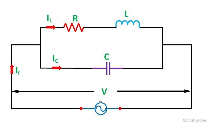
Input Network Schematic Diagram and Circuit Description
Careful inspection now shows that there are actually two parallel resonant circuits side by side. The left resonant circuit consists an inductor equal to L1 and‚Gallery of 1.draw circuit diagram of parallel resonance circuit :
Suggestion : Easy Tutorial 1 atico,1 altitude,1 aud to sgd,1 atico high tea,1 altitude menu,1 acre to sqf,1 atm to pa,1 atico wedding,1 anunnaki,1 atm,draw and guess,draw a perfect circle,draw and guess game,draw app,draw a cat,draw a dog,draw a box,draw a line meaning,draw a stickman,draw a line in the sand,circuit analysis,circuit app,circuit analysis ntu,circuit analysis calculator,circuit arrangement,circuit analysis for dummies pdf,circuit apk,circuit apk mod,circuit analysis problems and solutions pdf,circuit apartments,diagram app,diagram as code,diagram alir,diagram a sentence,diagram adalah,diagram a sentence for me,diagram about myself,diagram alur,diagram architecture,diagram alir penelitian,of all time meaning,of account,of age meaning,of all time,of ants and dinosaurs,of and for,of all things meaning,of all time or times,of all things,of a lifetime meaning,parallel axis theorem,parallel and series circuit,parallel angles,parallel and perpendicular lines,parallel apparel,parallel alpha,parallel app,parallel axis theorem formula,parallel angle rules,parallel arrangement,resonance album,resonance advisory pte ltd,resonance asia,resonance asset management,resonance and inductive effect,resonance antonym,resonance a level chemistry,resonance answer key,resonance agra,resonance allahabad,circuit analysis,circuit app,circuit analysis ntu,circuit analysis calculator,circuit arrangement,circuit analysis for dummies pdf,circuit apk,circuit apk mod,circuit analysis problems and solutions pdf,circuit apartments Free
Comments
Post a Comment